Difference between revisions of "TIGER documentation"
m (→DAQ PC) |
m (→DAQ PC) |
||
| Line 156: | Line 156: | ||
Maximum bandwidth = 1 Gbit/s = 125 MB/s | Maximum bandwidth = 1 Gbit/s = 125 MB/s | ||
| − | * Can easily accomodate data from more than | + | * Can easily accomodate data from more than 100 TM GEMROC modules |
* Can only accomodate data from 1 TL GEMROC module (only if UDP communication is optimized) | * Can only accomodate data from 1 TL GEMROC module (only if UDP communication is optimized) | ||
Revision as of 04:16, 6 June 2019
Contents
QDC mode[edit | edit source]
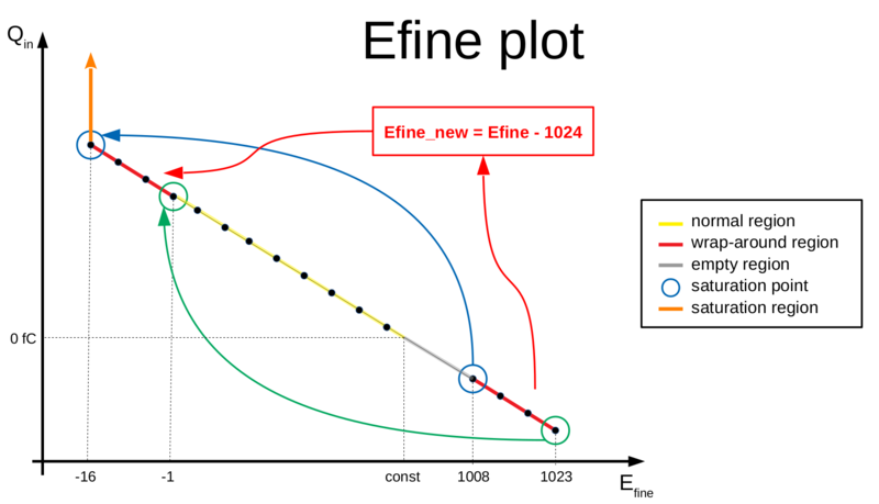
The counter for the ADC performing the charge digitization has a wrap-around effect such that very high signals (just below the saturation point) have 1008 < Efine < 1024.
For these values the measurement is still linear, so in order to apply the usual conversion using the calibration line (Efine = const + slope * Qin) we need first to shift them by 1024. Therefore we can define a new variable Efine_new given by:
- Efine_new = Efine (for Efine < 1008)
- Efine_new = Efine - 1024 (for Efine > 1007)
In this way, the values of Efine between (1008, 1023) are shifted to the region (-16, -1) and thus correspond to the very high charge signals, with Efine_new = -16 being the new value of saturation. This is explained in the Figure on the right and the Table below.
| Qin | Efine | Efine_new | Description |
|---|---|---|---|
| 5 | 385 | 385 | normal region |
| 10 | 340 | 340 | normal region |
| 15 | 295 | 295 | normal region |
| 20 | 250 | 250 | normal region |
| 20 | 205 | 205 | normal region |
| 30 | 160 | 160 | normal region |
| 35 | 115 | 115 | normal region |
| 40 | 70 | 70 | normal region |
| 45 | 25 | 25 | normal region |
| 46 | 16 | 16 | normal region |
| 47 | 7 | 7 | normal region |
| 48 | 1022 | -2 | wrap-around region, still linear -> apply Efine_new |
| 49 | 1013 | -11 | wrap-around region, still linear -> apply Efine_new |
| 50 | 1008 | -16 | saturation |
| 55 | 1008 | -16 | saturation |
| 60 | 1008 | -16 | saturation |
Rate considerations[edit | edit source]
TIGER[edit | edit source]
CGEM-IT setup:
- clock frequency = 160 MHz
- 2 Tx links per chip running at 160 MHZ SDR (Single Data Rate)
Chip maximum bandwidth = 320 Mbit/s
1 event word = 64 bits --> 80 bits with 8b/10b encoding
Chip maximum rate = 320 Mbit/s / 80 bit/event = 4 M event/s = 4 MHz
Channel maximum rate = 4 MHz / 64 channels = 62.5 kHz per channel
Frameword rate = 4.8 kHz per chip (equivalent to 76 Hz per channel increase)
GEMROC[edit | edit source]
TRIGGER-MATCH[edit | edit source]
Assumptions:
- 25 kHz rate per channel (noise + physics)
- 1.5 us time window
- 8 TIGER (512 channels)
- Two 64-bit header and trailer words for GEMROC packet
- Maximum L1 trigger frequency = 4 kHz
25 kHz per channel --> 1.6 MHz per chip
Number of hits per trigger = 1.6 MHz * 1.5 us = 2.4 hit/packet
Average packet size = 2.4 hit/packet * 64 bits (event word size) * 8 (TIGER) + 2 (header+trailer) * 64 bits = 1228.8 bits + 128 bits = 1357 bits = 170 bytes
Maximum trigger-matched data rate = 170 bytes * 4 kHz = 680 kB/s = 5440 kbit/s per GEMROC
TRIGGER-LESS[edit | edit source]
Assumptions:
- 25 kHz rate per channel (noise + physics)
25 kHz per channel --> 1.6 MHz per chip
Trigger-less data rate = 1.6 MHz * 8 (TIGER) * 64 bits (event word size) = 819.2 Mbit/s = 103 MB/s per GEMROC
DAQ PC[edit | edit source]
1 GbE link
Maximum bandwidth = 1 Gbit/s = 125 MB/s
- Can easily accomodate data from more than 100 TM GEMROC modules
- Can only accomodate data from 1 TL GEMROC module (only if UDP communication is optimized)

