TIGER documentation
Contents
QDC mode[edit | edit source]
In QDC mode the charge is measured by sampling the peak voltage of the Energy branch shaper. The sampling time window duration can be programmed by the user through the channel configuration registers (max_integ_time and min_integ_time). These two parameters must be set with the same value and the sampling time duration is given by:
where [math]T_{clk} = 6.25ns[/math] is the system clock period.
Settings[edit | edit source]
In order to operate the chip in S&H mode the following configuration registers must be set as follows:
- integ_en = 1
- qdc_mode = 1
Data decoding[edit | edit source]
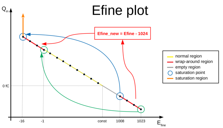
The counter for the ADC performing the charge digitization has a wrap-around effect such that very high signals (just below the saturation point) have 1008 < Efine < 1024.
For these values the measurement is still linear, so in order to apply the usual conversion using the calibration line (Efine = const + slope * Qin) we need first to shift them by 1024. Therefore we can define a new variable Efine_new given by:
- Efine_new = Efine (for Efine < 1008)
- Efine_new = Efine - 1024 (for Efine > 1007)
In this way, the values of Efine between (1008, 1023) are shifted to the region (-16, -1) and thus correspond to the very high charge signals, with Efine_new = -16 being the new value of saturation. This is explained in the Figure on the right and the Table below.
| Qin | Efine | Efine_new | Description |
|---|---|---|---|
| 5 | 385 | 385 | normal region |
| 10 | 340 | 340 | normal region |
| 15 | 295 | 295 | normal region |
| 20 | 250 | 250 | normal region |
| 20 | 205 | 205 | normal region |
| 30 | 160 | 160 | normal region |
| 35 | 115 | 115 | normal region |
| 40 | 70 | 70 | normal region |
| 45 | 25 | 25 | normal region |
| 46 | 16 | 16 | normal region |
| 47 | 7 | 7 | normal region |
| 48 | 1022 | -2 | wrap-around region, still linear -> apply Efine_new |
| 49 | 1013 | -11 | wrap-around region, still linear -> apply Efine_new |
| 50 | 1008 | -16 | saturation |
| 55 | 1008 | -16 | saturation |
| 60 | 1008 | -16 | saturation |
ToT mode[edit | edit source]
The Time-over-Threshold mode allows to measure the charge of the input signal from the pulse duration.
- It is typically performed on the T-branch shaper because of its better timing performance and thus depends on the threshold applied on this branch (VTH_T1)
- The ToT curve intrinsic non-linearity is due to the CR-RC shapers typical response
Settings[edit | edit source]
In order to operate the chip in ToT mode the following configuration registers must be set as follows:
- integ_en = 0
- qdc_mode = 0
Data decoding[edit | edit source]
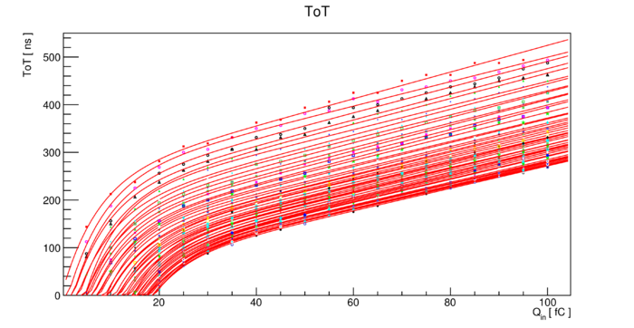
- The ToT curve depends on the threshold level, thus the ToT measured on each channel can be converted into the correspondent input charge by applying the correct calibration curve (see Figure on the right)
- The ToT curves are fitted with the following function:
- These curves must be inverted in order to retrieve back the input charge information
- Channel-by-channel TDC calibration files can be applied in order to improve the time binning of this measurement, otherwise limited to the clock period (6.25 ns)
Output words[edit | edit source]
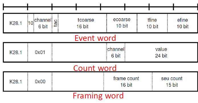
Event word[edit | edit source]
- identified by header 0b10
- 64 bits
- includes digitized information for each hit
Count word[edit | edit source]
- identified by header 0x01
- 64 bits
- includes information about internal counters
Framing word[edit | edit source]
- identified by header 0x00
- 64 bits
- sent with top priority after each 2^15 clock cycles (1 frame = 204.8 us)
- includes information about frame word used for time reference and SEU count detected for each frame


